
| Home | Price List | Order Info | P955H Course | PIR & RF Data | Mini Course |
|
Building GPIC28sov6 Training Circuit |
|
|
| The kit version of the GPIC28sov6 is supplied with the PIC18F26K22 fitted. The GPIC28sov6 PCB is lead free so it is best to solder the components using lead free solder with a flux which does not need to be cleaned. |
|
|
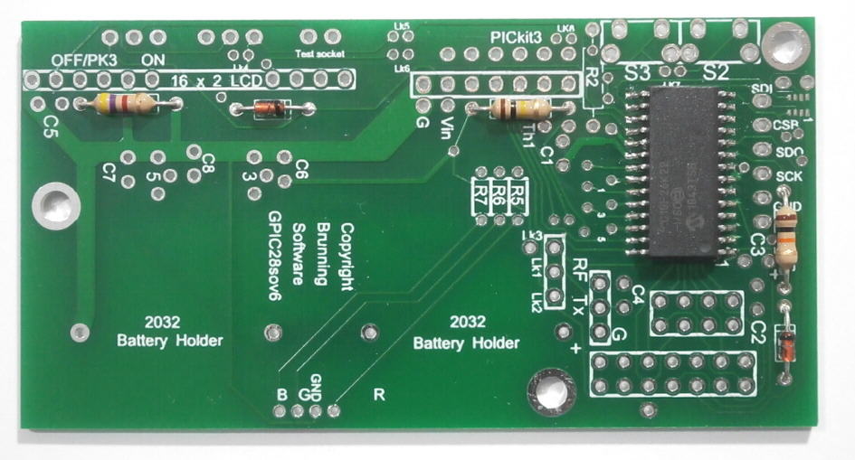
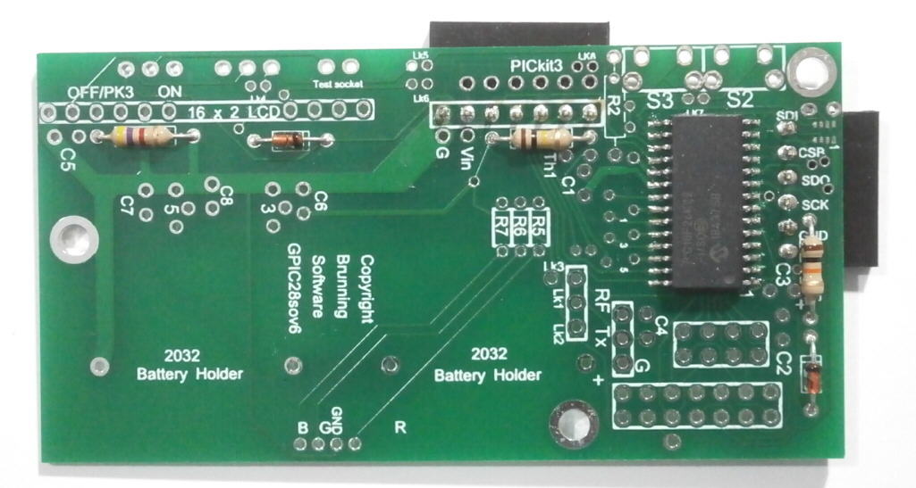
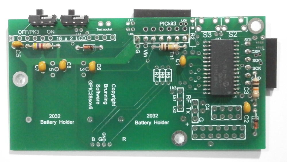
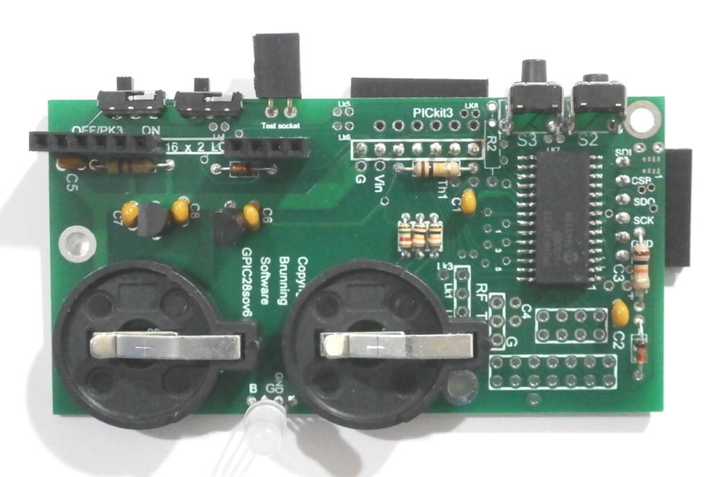
Begin by fitting and soldering three resistors and two diodes:- Before fitting R1 look carefully at the PCB. At the end of R1 nearest to D1 there are two holes in the PCB. R1 MUST be fitted into the hole nearest to D1 as shown in the picture. R1 = 10k R3 = 100k R4 = 4k7 D1 = 1N4148 D2 = 1N4148 R2 is not usually fitted |
|
|
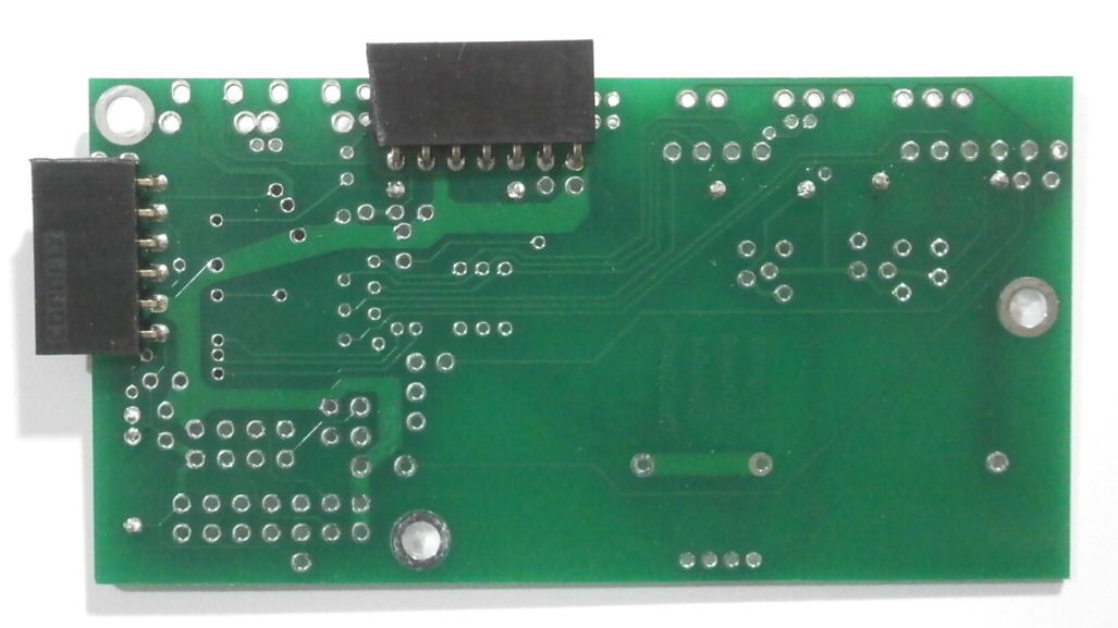
Fit and solder 6 way and 7 way right angle sockets on the underside of the PCB:- 6 way socket connects to GY-BM circuit with BMP280 fitted 7 way socket connects to P205 programmer or to PICkit3 via 6 to 7 pin adaptor |
|
|
A 6 pin plug can be fitted instead of the 7 pin socket so that PICkit3 can be plugged directly to the GPIC28sov6. But if this is done the box will have sharp pins poking out of it and the circuit is less flexible. By fitting the 7 way socket it allows either the P205 programmer or PICkit3 to be used. P205 can be used to exchange data with your own programme on your PC - more about this later. |
|
|
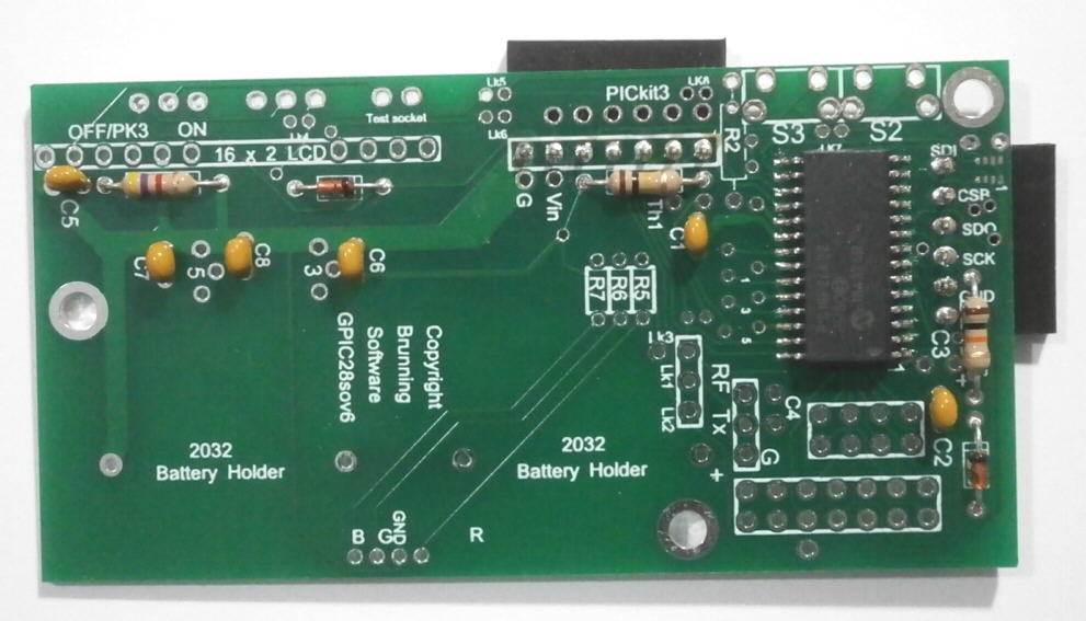
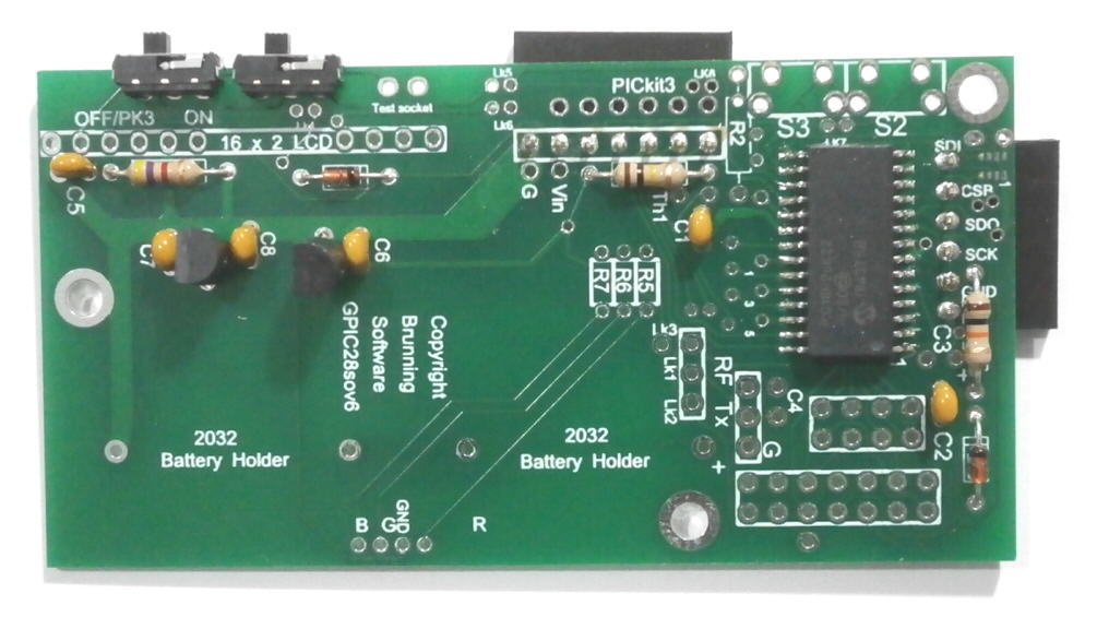
Fit and solder:- C1, C2, C5, C6, C7, C8 = 1uF ceramic capacitor |
|
|
Fit and solder two miniature switches Left = Power on/off, Right = LCD on/off |
|
|
Fit and solder 3v regulator and 5v regulator |
|
|
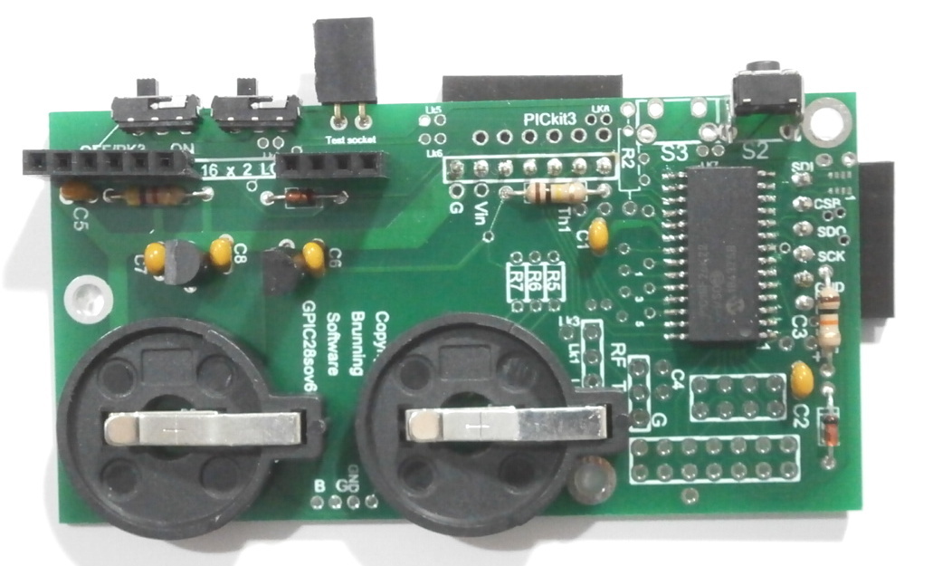
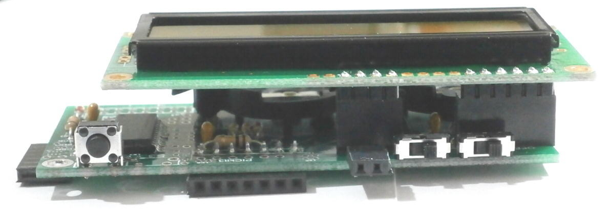
Fit and solder:- Two 2032 coin cell holders. 6 way and 4 way sockets for LCD. Push switch S2 with short button. The two pin test socket is optional. The picture shows this socket mounted horisontally but now a verticle socket is used. This socket connects across the on/off switch so the total battery current can be measured when switched to off. |
|
|
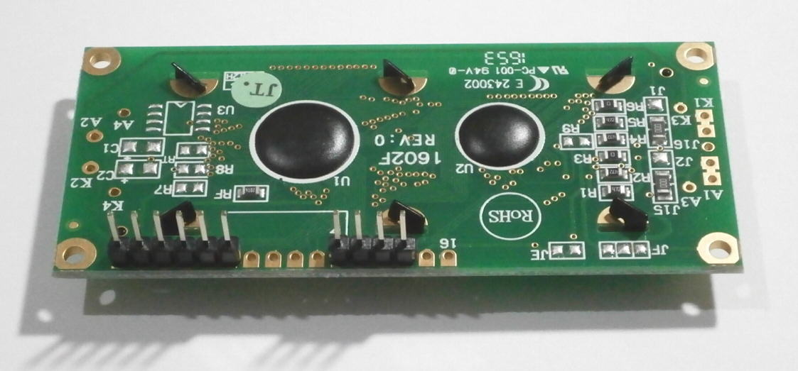
Fit and solder 6 pin and 4 pin plugs to the underside of the LCD |
|
|
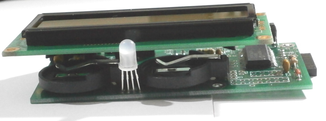
The LCD plugs into the GPIC28sov6. |
|
|
Fit and solder:- R5 = 10k miniature resistor R6 = 10k miniature resistor R7 = 1k5 miniature resistor S3 = Push button with long button |
|
|
Fit and solder RGB LED The long lead MUST go into the hole marked GND. You may prefer to fit the RGB LED after you have cut the holes in the box. That will allow the LED to be placed neatly through its own hole in the box lid. |
| Home | Price List | Order Info | P955H Course | PIR & RF Data | Mini Course |